The Big Picture of the Link Layer
The link layer operates between the network layer (Layer 3) and the physical layer (Layer 1), facilitating communication between adjacent nodes in a network path.
Terminology
- Nodes: Hosts and routers (at the link layer, they are equivalent as transmitters/receivers)
- Links Communication channels connecting adjacent nodes
- Frames: The packet format at the link layer; each frame encapsulates one network layer datagram
Important
The link layer’s primary responsibility is transferring datagrams from one node to a physically adjacent node over a link.
Link Layer in the Communication Path
When a packet travels from source to destination, it traverses multiple hops, with each hop potentially using a different link layer protocol:
- Different hops may use different protocols (e.g., Wi-Fi on one hop, Ethernet on another)
- Each hop implements its own link layer services independently
graph LR
    A[Source Host] --> B[Router 1]
    B --> C[Router 2]
    C --> D[Router 3]
    D --> E[Destination Host]

    A-. "Link 1: WiFi" .->B
    B-. "Link 2: Ethernet" .->C
    C-. "Link 3: Fiber" .->D
    D-. "Link 4: Ethernet" .->E
Link Layer Services
Framing and Link Access
Framing is the process of encapsulating network layer datagrams into link layer frames. A frame typically consists of:
- Header: Contains link layer control information
- Payload: The encapsulated network layer datagram
- Trailer: Contains error detection bits and other control information
Link Access Methods
- Point-to-point links: Direct connection between two nodes
- Broadcast channels: Shared medium where multiple nodes can transmit (requires addressing and access coordination)
Reliable Data Transfer (RDT)
Some link protocols provide reliable delivery between adjacent nodes, while others do not:
- Protocols WITH RDT: Wi-Fi (uses stop-and-wait)
- Protocols WITHOUT RDT: Ethernet (relies on low bit error rates)
When is RDT Needed?
-
Wireless links: High bit error rates due to interference → RDT beneficial
-
Fiber optic links: Very low bit error rates → RDT unnecessary overhead
Exam Question
Why does Wi-Fi use stop-and-wait instead of go-back-N?
Since Wi-Fi is usually used for short distances with low latency, the simpler stop-and-wait protocol is sufficient and avoids the complexity of go-back-N.
Wi-Fi is half-duplex, making stop-and-wait easier to implement.
Why do we have both link-level and end-to-end reliability?
Link-level reliability deals with noise, bit errors, and short-term interference on a single physical or wireless link, where local retransmissions are fast and cheap.
End-to-end reliability must cope with congestion drops, routing changes, reordering, and failures anywhere along a multi-hop path, which hop-by-hop mechanisms cannot fully see or correct.
Flow Control
Manages the data transmission rate between nodes to prevent overwhelming the receiver. Common implementation approaches includes:
-
XON/XOFF protocol: Simple binary feedback (stop/go)
-
Window-based protocols: Used for long-distance links (e.g., undersea cables)
-
Stop-and-wait: Common for short-distance links
Error Detection and Correction
Error Detection
- Detects errors caused by signal attenuation, noise, etc.
- Upon detection: requests retransmission or drops the frame
- Techniques: Checksums, CRC (Cyclic Redundancy Check)
Error Correction
- Forward Error Correction (FEC): Allows receiver to correct errors without retransmission
- Used when: Receiver cannot send acknowledgments (e.g., power-constrained devices)
- Trade-off: Requires significant redundancy bits (high overhead)
Note
FEC is rarely used due to the high overhead cost. It’s typically reserved for special cases where retransmission is impossible.
Duplexing
Determines how data flows over the link:
-
Half duplex: Nodes take turns sending and receiving
- Common in: Wi-Fi (due to hardware limitations)
- Radio switches between transmit and receive modes
-
Full duplex: Simultaneous sending and receiving
- Common in: Wired networks
- Requires dedicated channels for each direction
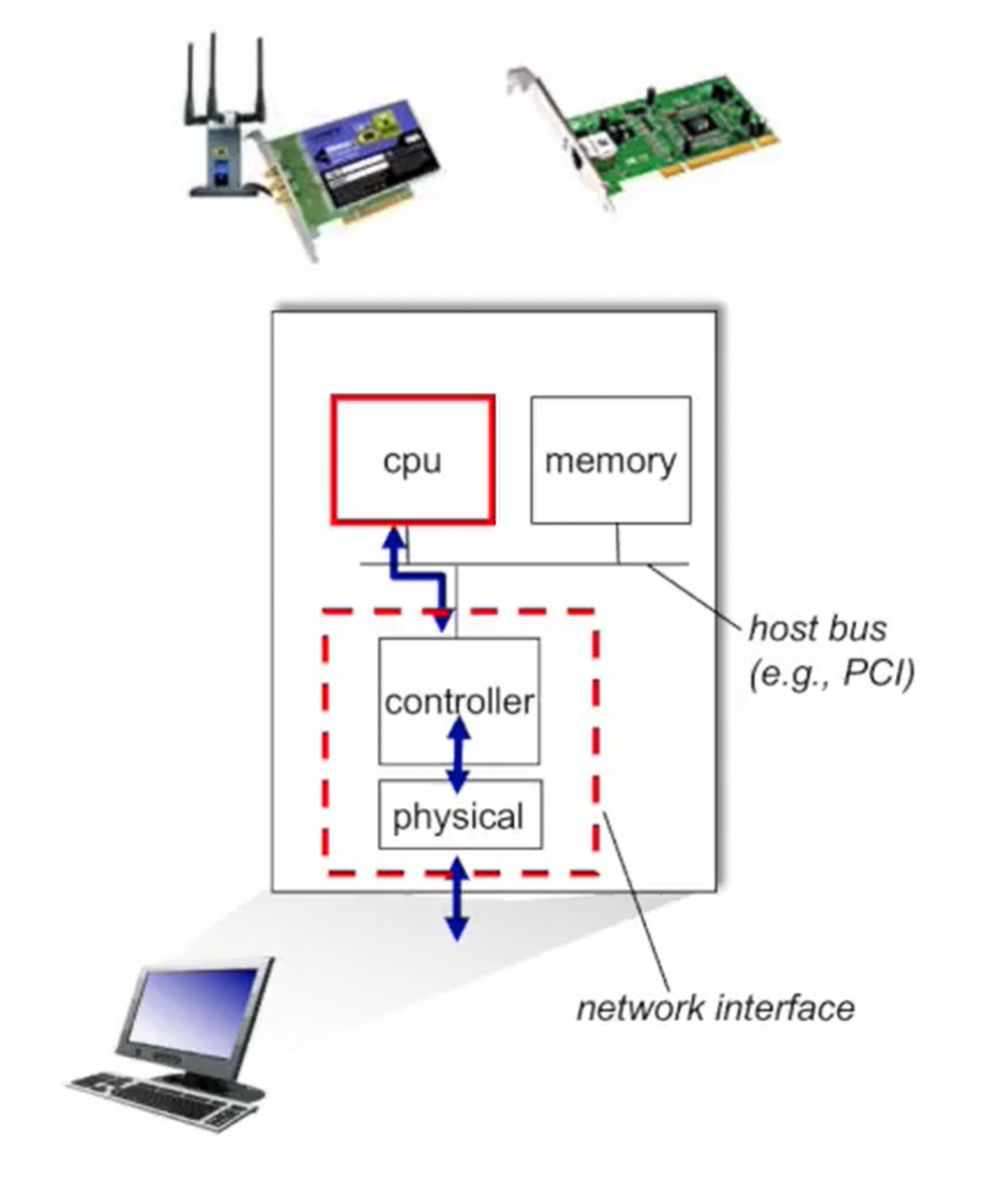
Link Layer Implementation
Hardware Components
The link layer is primarily implemented in:
- Network Interface Card (NIC): The main hardware component
- Controller chip: Implements the link layer protocol
- Physical layer chip: Handles signal transmission/reception
Frame Transmission Process
Transmission Side (Tx)
- Network layer passes datagram to link layer
- Link layer frames the datagram:
- Adds header with control information
- Adds trailer with error detection bits
- Includes flow control and RDT information if needed
- Frame passed to physical layer for transmission
- Physical layer converts bits to signals:
- Light pulses for fiber optic
- Radio waves for wireless
- Electrical signals for copper cables
Reception Side (Rx)
- Physical layer receives signals and converts to bits
- Passes frame to link layer
- Link layer performs:
- Error checking using detection bits
- RDT verification if applicable
- Flow control management
- Extracts datagram from frame
- Passes datagram to network layer
Important
Each hop in the network path independently implements its own link layer protocol. The receiving node may then become a transmitter for the next hop, potentially using a completely different link layer protocol.